When terminating an RF transmission line why do we use two 100 ohm resistors in parallel instead of one 50 ohm resistor? This is a common way to get a better match.
It has to do with the current distribution in the microstrip line. The current density of a microstrip transmission line is highest at the edges – and for that reason a better match over a broader frequency range is easier to achieve using two 100 ohm resistors placed at the edges for the 50 ohm resistor.
This is a well-documented phenomenon, and it is easy to show this behavior in a simulation and in practice.
Below is a Sonnet model of a 50 ohm resistor placed at the end of a 50 ohm microstrip line – terminating the incoming wave.
Although Sonnet is a 2.5D simulator – with a bit of work we can create a 3D model. It is important to point out that a Method of Moments places constraints on currents traveling in the Z-axis.
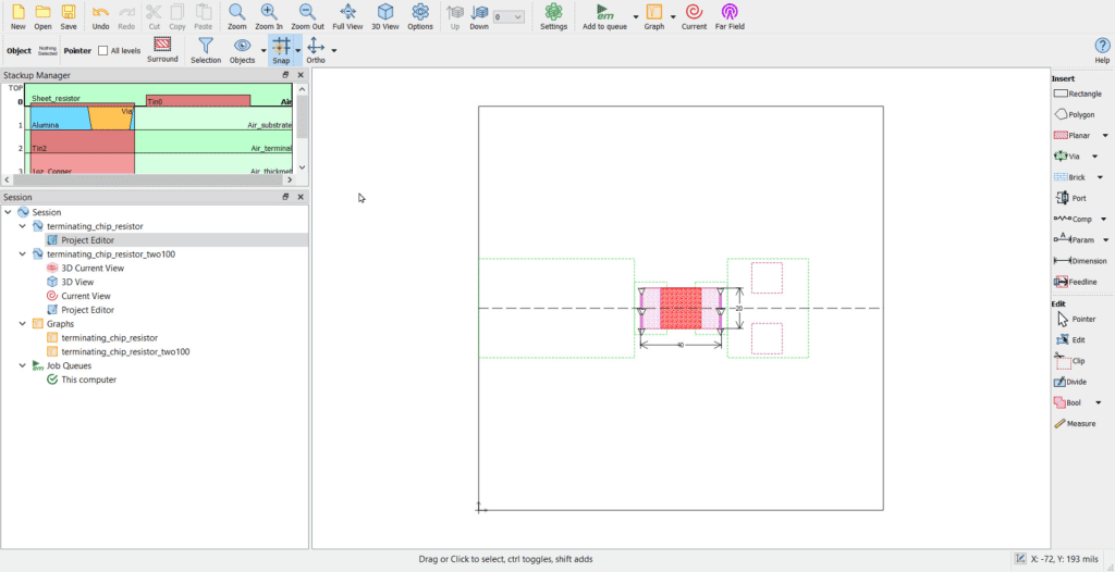
On the left is a 50 ohm microstrip line. In the center is a 3D model of the 402 size resistor with two 15 mil square vias to ground. The substrate is Rogers RO3003 with a dielectric constant of Er=3.0.
The screen capture below shows the 2D view in Sonnet Software.
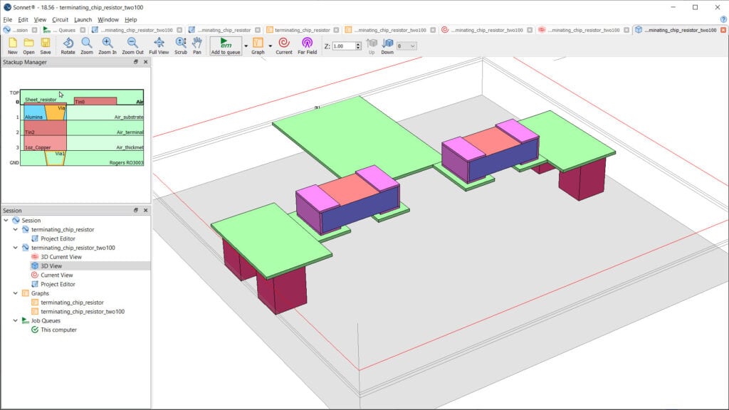
Below is a 3D rendering of this model. The model includes an alumina brick (blue). The sheet resistance (orange) is 50 ohm square and is placed between the terminals (pink) and above the dielectric brick.

An electromagnetic (EM) Simulation was performed from 0.1GHz to 10GHz. Below shows the results of this simulation – the magnitude of S11 – or return loss.
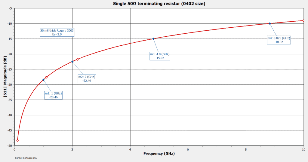
Return loss is better than -20dB at frequencies below about 2.6GHz and crosses -15dB at 4.8GHz. This is fine for many applications.
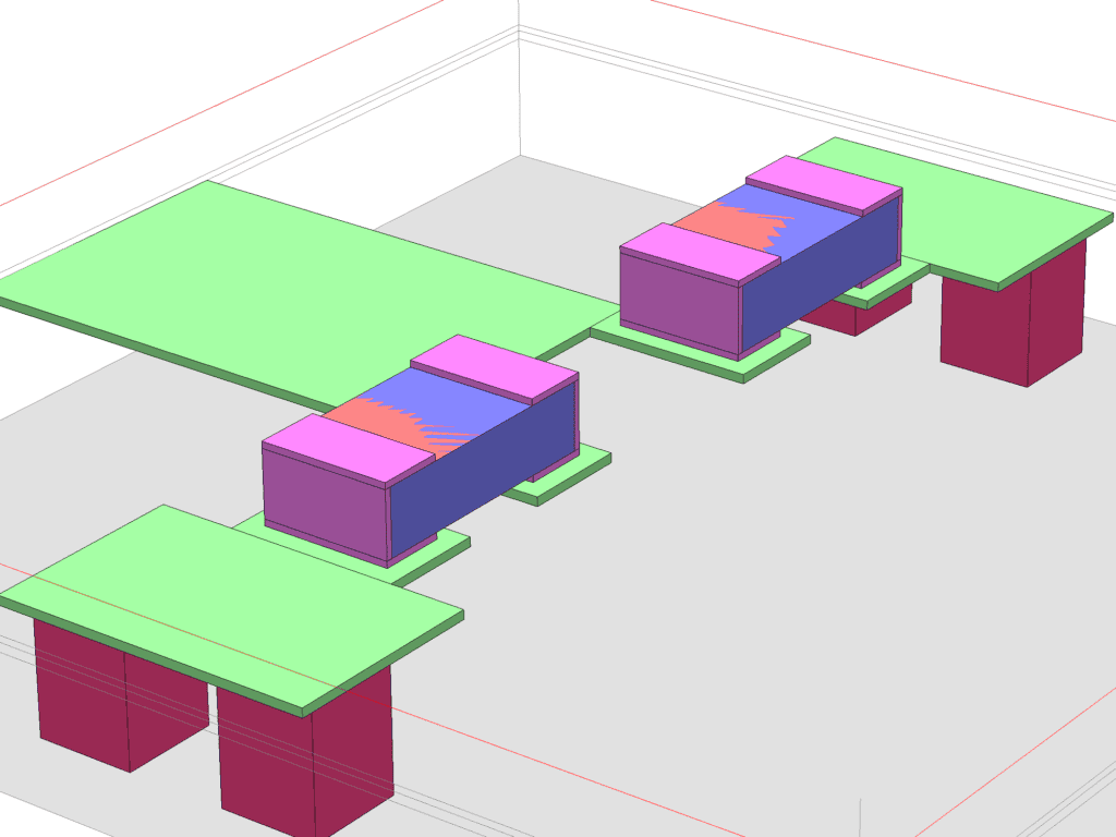
For better return loss two 100 ohm resistors can be used as shown in the Sonnet 3D model.
This simulation shows much better results – with a great return loss improvement .
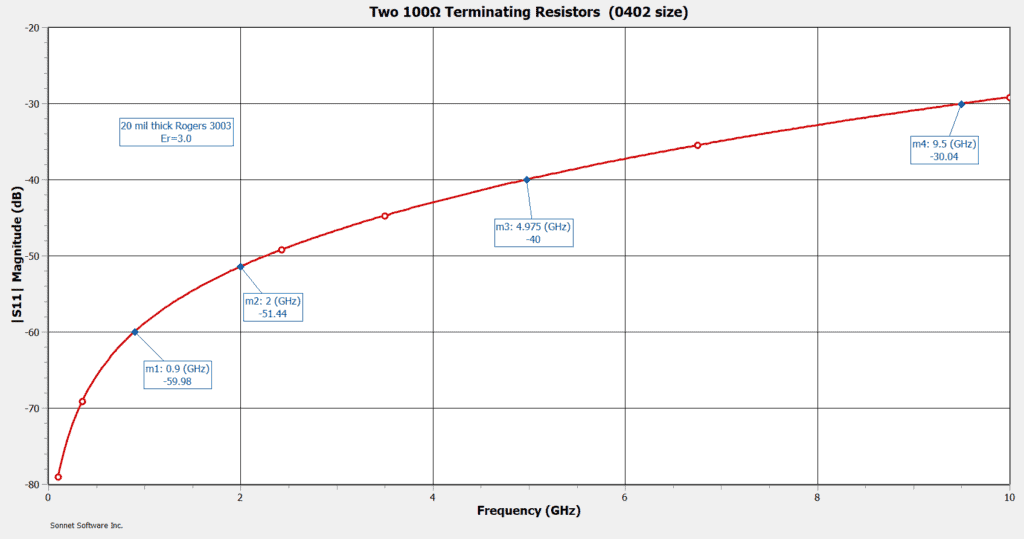
Return loss remains below -30dB up to 9.5GHz.
Below shows a current density plot at 2.4GHz. Since current density is higher at the edges of a microstrip transmission line it makes more sense to place a terminating resistor at the edges of the microstrip. In this case two 100 ohm resistors are used instead of a single 50 ohm resistor.
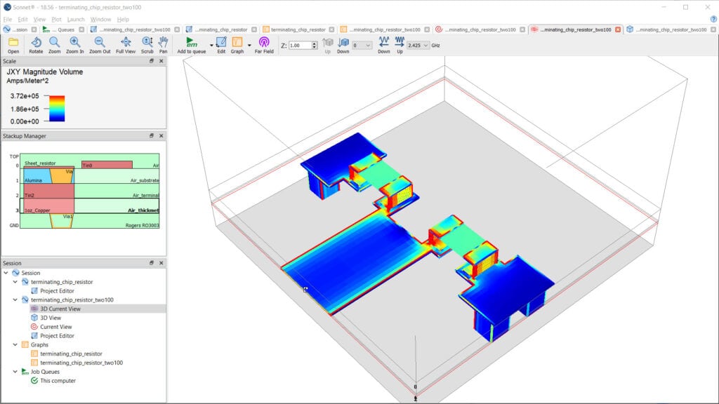
2D current density plot at 2.4GHz
