Improving Return Loss Using Two 100-Ohm Terminating Resistors
When terminating an RF transmission line, why might we use two 100 Ω resistors in parallel instead of a single 50 Ω resistor? Using two resistors can provide a better impedance match over a broader frequency range.
This improvement is related to the current distribution within a microstrip transmission line. The current density is highest near the edges of the microstrip conductor. Consequently, placing a 100 Ω resistor near each edge can provide a better broadband match than placing a single 50 Ω resistor at the center of the conductor.
This behavior is well documented and can be demonstrated through electromagnetic simulation and measurement.
The Sonnet model below represents a single 50 Ω resistor placed at the end of a 50 Ω microstrip transmission line.
Sonnet is primarily a 2.5-D electromagnetic simulator, but with additional modeling, it can be used to represent a three-dimensional resistor structure. The method-of-moments formulation places certain constraints on how current flowing in the z-direction is represented.
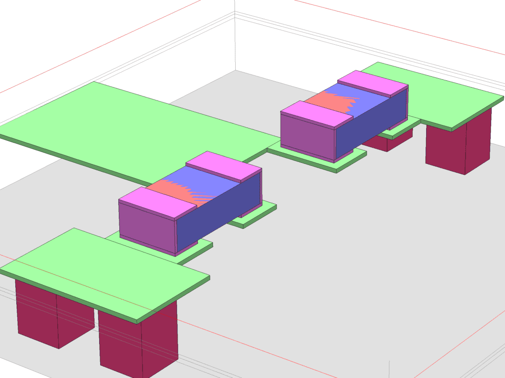
A 50 Ω microstrip transmission line is shown on the left side of the model. In the center is a three-dimensional representation of an 0402 resistor connected to two 15 mil × 15 mil ground vias. The substrate is Rogers RO3003 laminate with a relative permittivity of εr = 3.0.
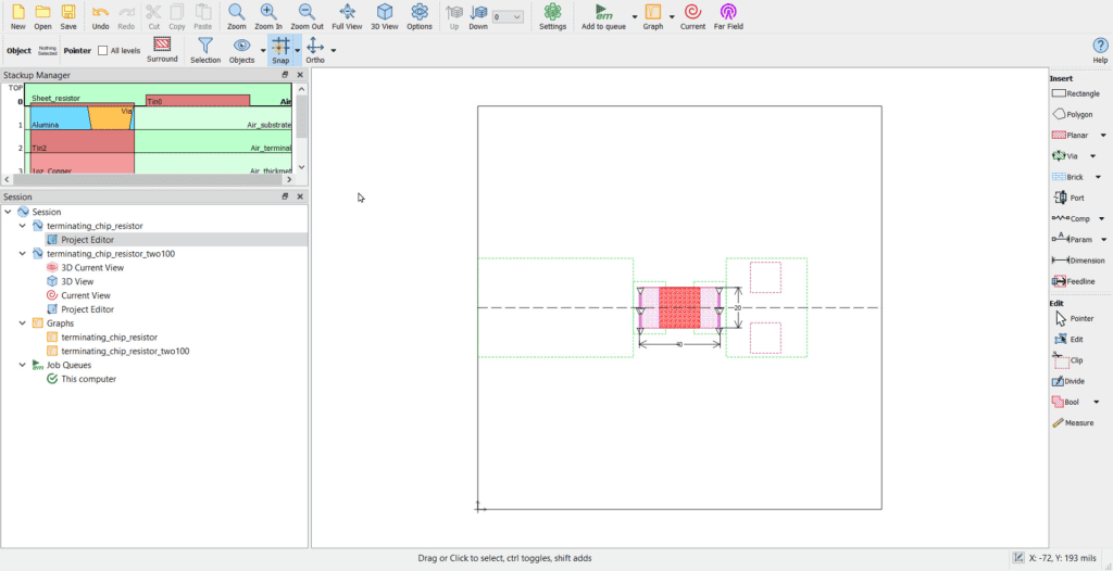
The image below shows the two-dimensional view of the model in Sonnet Software.
The three-dimensional rendering of the model is shown below. The model includes an alumina body, shown in blue. A resistive sheet, shown in orange, has a sheet resistance of 50 Ω/□ and is placed between the terminals, shown in pink, above the alumina body.

An electromagnetic simulation was performed from 0.1 GHz to 10 GHz. The plot below shows the magnitude of S11 in decibels.
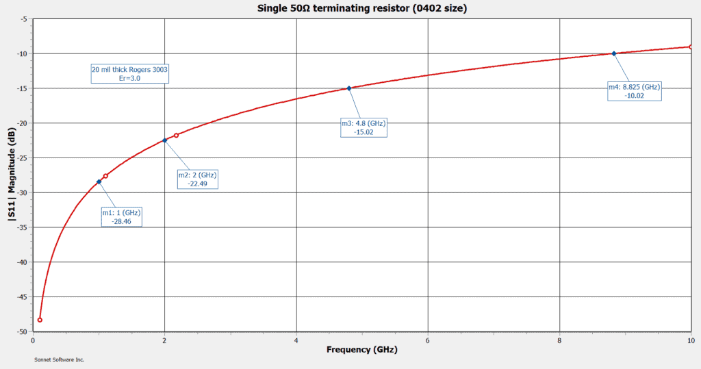
S11 remains below −20 dB at frequencies below approximately 2.6 GHz and reaches −15 dB at approximately 4.8 GHz. This performance is acceptable for many applications.
To improve the broadband match, two 100 Ω resistors can be connected in parallel, as shown in the Sonnet three-dimensional model below.

The two-resistor termination produces a substantial improvement in the simulated impedance match.
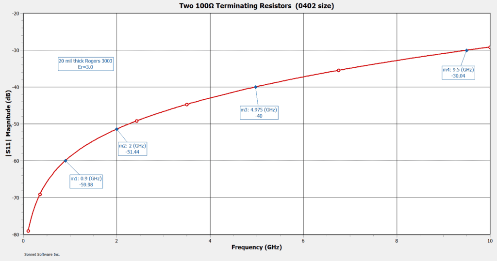
With the two-resistor termination, S11 remains below −30 dB through approximately 9.5 GHz. This corresponds to a return loss greater than 30 dB over that frequency range.
The following current-density plots illustrate the current distribution at 2.4 GHz. Because the current density is highest near the edges of the microstrip conductor, placing a terminating resistor near each edge produces a better broadband match. In this example, two 100 Ω resistors are used in parallel instead of a single 50 Ω resistor.